
Written by: Rohan Tulsiani
About the Author: Rohan Tulsiani is a 21-year-old undergraduate Computer Science student at the University of Southern California. Rohan works as a Teacher Assistant for ITP485, which is USC’s undergraduate Game Engine class.
Abstract
With the advent of Virtual Reality and other major advances in the field of computer graphics, video games have become increasingly realistic. If you compare a current video game with one from 10, or even 5, years ago, it is easy to see just how much more life-like today’s video game titles look, in huge part due to the relative power of modern personal computers (PC). Yet, even assuming top-tier hardware, the beautiful character and environment models many gamers take for granted in games like Mario would not be possible without the 3D modeling standards and processes often used during a game’s development. So, next time you load up your favorite video game, keep in mind the intricate details needed to make the image you see on your screen possible.
Intermingling Between the Virtual and Physical World
These days, for better or for worse, video games are becoming an integral part of global culture. Interestingly, video games are now considered to be a sport, demonstrated by their appearance at the Asian Games 2018 [2]. Parents are even hiring tutors to teach their kids to win at various games, so as to pursue a career of Live Video Streaming or E-Sports, which in earlier years would have been considered absolutely absurd [1]. Given this spotlight on video games, fans may wonder how video games, and the characters they adore, are actually built. Since Mario is a very well-known video game character, this article will explain, using him as a reference, the various steps and data needed to construct a 3D Mario from scratch.
Constructing Mario’s Body
Computer Screens are virtually two dimensional, making it incredibly easy to display a 2D image; the mapping between the image’s dimensions and the screen’s dimensions is one-to-one. A 2D image, such as a triangle, can be easily drawn onto a 2D surface like a piece of paper without any translation. Unfortunately, drawing a 3D model on a computer monitor is more of a challenge, because there is no simple mapping between 2D and 3D space. A 3D image, such as a sphere, cannot be drawn onto a 2D surface without losing some information; it requires an illusion of depth that is not trivial to create. Our reality is 3D, so a simple way to imagine the inherent complexity of describing a 3D object in a 2D plane is to imagine what a 4D object would look like in real life; this is appropriately incomprehensible for most people.
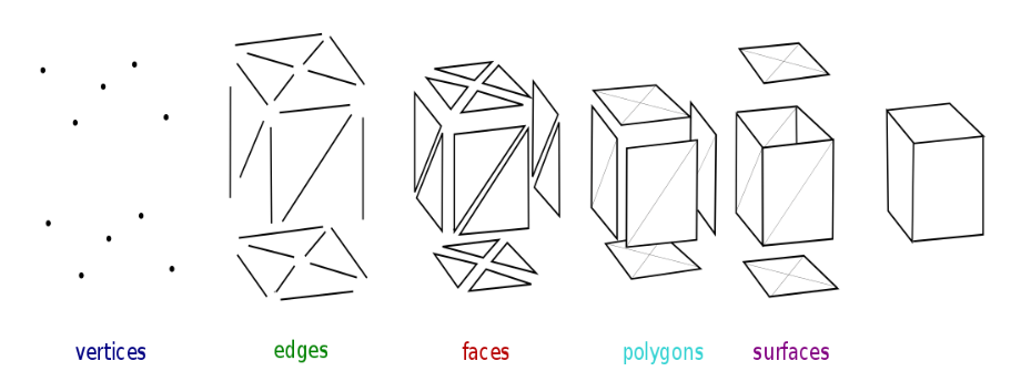
Figure 1: Image showing the various different primitives that make up a 3D model [9].
The smallest unit of a 3D model is called a vertex; hence, in order to understand 3D computer graphics, an understanding of vertices is fundamental. Vertices can be thought of as little dots in a 3D coordinate system. Thus, every vertex is assigned a 3D position, which specifies its horizontal and vertical position, like in a 2D coordinate system, as well as a depth into or out of the screen. An object further into the screen will appear smaller, like it would in reality. As shown in Figure 1, these vertices are connected into triangles, the simplest polygonal shape. Next, the triangles are combined together to form a 3D model. Unfortunately, in practice, the process of building a character model is not as simple as assigning vertices a 3D coordinate; while the position of a vertex allows 3D modellers to dictate the general shape of their character, it does not give the character traits like color or movement.

Figure 2: Demonstration of how Mario is made up of many vertices, connected together [10].
The left section of Figure 2 shows a Mario with only its vertex positions specified, the right section shows a completed Mario. Clearly, we still have a ways to go before we have a complete model.
Giving Mario Skin
Now that Mario’s vertex positions have been specified, he is beginning to look more like his in-game counterpart, but he is still completely devoid of color or clothing. With 3D graphics, adding color to a model like Mario is no trivial task. In 2D, an artist could create an outline for Mario, then just color in his skin and clothes. Although Mario’s vertex positions act as an outline in 3D, coloring in that outline is not so simple: to draw directly onto a 3D model, artists need to specify vertices that encode the exact start and end positions of each shape. To draw a purple square, for example, the artist would need to explicitly specify the 4 vertices that form the square, then fill that space with purple. This is not too difficult for a simple object like a square, but it becomes difficult when working with complex 3D models, some of which have millions of vertices.
The challenge of tackling the complexity of 3D coloring encourages its artists and engineers to use a technique called UV mapping. As previously mentioned, a 3D model is simply a large amalgam of 2D polygons connected together. For example, each face of a cube is actually just a square. An artist can therefore draw six 2D images, one for each face of the cube, then just choose which image corresponds to which face, instead of drawing directly onto the cube. Thus, if an artist draws a 2D texture, it is possible to map that 2D texture (or a specific portion of it) onto the polygons that make up a 3D model, since both the polygons and the texture are two dimensional. A 2D to 3D mapping, like the one mentioned above, can be thought of as drawing six different images on a piece of paper, such that when that paper is folded into an origami cube, each image on the flattened 2D paper maps directly to a face on the 3D cube. A 2D texture that is projected onto a 3D model is called a UV Map.

Figure 3: How a UV Map can be used to map segments of a 2D texture onto a 3D object [7].
In Figure 3, the left image is a 3D model of a monkey, and the right image is the UV Map that is being used to color the monkey model in. Each of the little grids that run across the monkey’s face in the left-hand image are the 2D polygons that make up the 3D monkey. Each polygon is mapped onto a segment of the UV Map. In this case, the polygons that make up the monkey’s head are mapped to the hair part of the UV Map, whereas the polygons that make up the monkey’s face map to the parts of the UV Map that have a flesh color.

Figure 4: UV map of Mario from the game Mario 64 [10].
The above UV map of Mario is similar to the monkey, in that each of Mario’s polygons was flattened out onto a set of 2D shapes that were simply colored in, like a regular 2D image, then folded back up into a 3D Mario. Hence, upon application of the UV map, Mario’s skin will be assigned a flesh color, whereas his overalls will be assigned a denim blue; the yellow outlines on the UV map show the polygons a particular part of the Mario UV map texture corresponds to.
How Mario Reacts to Light
In our 3D reality, light works due to particle reflection; photons of light reflect off surrounding objects, allowing us to visually perceive those objects’ existence. Yet, modeling the precise movements and reflections of an uncountable number of photons is a complex sequence of events difficult for a computer to simulate, especially given that video games are calculating these simulations in real-time (unlike animated films, for instance). Thus, video games often use a simplified model of real-world lighting. Though not perfect, this system is a happy medium between computational complexity and graphical fidelity, since it sacrifices a small amount of realism for a large boost in speed. The Phong Reflection Model, which will be described below, is the most popular model for simulated lighting used in modern video games.
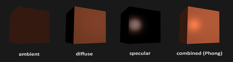
Figure 5: Illustration of the 3 components of the Phong Reflection Model [3].
Under the Phong Reflection Model, any 3D object in the game world consists of three different values: an ambient color, a diffuse color, and a specular color. First, an ambient color defines how much an object is lit even if it is not exposed to any light source in particular. An object’s ambient color is used to account for the effect of distant light sources, like the sun or moon, which color the entire environment, regardless of whether there is a particular light source acting on a model. Next, the object’s diffuse color dictates the solid color that an object will be assigned if it has a light shining directly onto it. Finally, the specular color accounts for an object’s “shininess;” a metal object would probably have a more bright specular color than a plank of wood, since metal is able to reflect light better than wood is [6].
Overall, Phong lighting in games relies on three fundamental pieces of information: the distance from a vertex to the light source; the ambient, diffuse, and specular color values; and the direction a particular vertex is facing. In 3D, one can calculate the distance between a specific vertex and a light source by simply subtracting the X, Y, and Z components of their coordinates from one another; the further a light is from an object, the less the light source brightens that object. Next, a 3D object’s ambient, diffuse, and specular color values dictate how they react to a light source; an object with a bright specular color, for instance, looks shinier. However, for lighting to work, we still need to know the facing of a specific vertex on the model. If a character is facing away from the light, then we expect the area encompassed by all its back-facing vertices to be lit up, whereas the area encompassed by all its front-facing vertices should be comparatively dark; this is the primary mechanism by which Phong is able to approximate real world lighting so precisely [8]. Fortunately, there is a mathematical construct called a vector, which is often used to encode direction in both games and physics.

Figure 6: Example of a simple Vector [9].
As shown in Figure 6, the 2D vector (2, 3) encodes an arrow that points 2 units to the right, and 3 units upwards. Similarly, in 3D, mathematicians and graphics programmers alike use vectors to encode 3D direction. In 3D, a special vector called a normal vector, one that points in the same direction that its corresponding object is facing, is often used for lighting calculations. Using 3D normal vectors, one can calculate the angle between an object’s orientation and the light reflecting off of the object; the smaller the angle, the more directly the light is hitting that object, thus brightening it.

Figure 7: Normal Vectors on Mario [11].
Figure 7 shows how the idea of normal vectors can be applied to Mario. In Figure 7, the red arrows denote normal vectors. Notice how Mario’s head has normal vectors that point upwards, indicating that it would be most lit up if shone upon by an overhead light. Similarly, the tip of Mario’s nose has normal vectors pointing out of the screen, indicating that it would be most lit up by a light shining from in front of him. Thus, with normal vectors added to the equation, it is possible to simulate lighting in a 3D world, in a fairly precise fashion.
Building Mario’s Skeleton
The last fundamental component needed to build a game-ready Mario, from scratch, is a skeleton. All the previous 3D modelling techniques enable a game team to build a 3D model that looks like Mario, but that 3D model is still incapable of human-like movement; it is completely static. Thus, we need to employ skeletal animation to make our Mario more dynamic.

Figure 8: Diagram of the bone hierarchy used during Skeletal Animation [4].
In 3D computer graphics, skeletal animation works by assigning vertices to a hierarchy of bones; this is similar to real life, where if you move a limb, like your leg, multiple other body parts move with it, like your feet and knee. Therefore, for any skeletally animated 3D model, each vertex is assigned to a particular bone, and each bone is assigned a parent bone. Hence, whenever a bone or its parent bone move, all the vertices attached to either of those bones move as a unit. If Mario, for example, moves his shoulder, his arm should move with it, which should, if animated correctly, move his hand; in other words, the hand is a child of the arm, which is a child of the shoulder. Because a 3D model can have millions of vertices, artists do not want to be concerned with how to animate a 3D model on a vertex with individual detail, rather they want to be able to animate large sets of vertices at a time for human-like movement; skeletal animation perfectly suits this purpose.
The 3D model’s skeleton can then be configured in various different orientations, called keyframes, which are just snapshots of a 3D model in various poses, that when played back in quick succession form a complete animation. So, a sprinting animation might consist of rotating the knee bone by 45 degrees in a specific direction, so as to simulate the knee bending, then moving that knee’s corresponding foot upwards by a few units, to simulate the foot lifting off the ground.
The Game Engine
A 3D modeller, after specifying Mario’s 3D vertex positions, UV maps, ambient, diffuse, and specular lighting values, 3D normal vectors, and skeletal animation keyframes, is finally ready to see the 3D Mario model in an actual game. The 3D modeller, however, upon exporting Mario from whatever program he or she used to model Mario, observes not a 3D rendered model but a bunch of crazy looking plain text.

Figure 9: Sample 3D Model Output.
As previously noted, 3D is a lot harder of a problem than 2D as there is no direct mapping from 3D to a 2D screen. Therefore, different 3D models can be exported and displayed with very different formats, meaning a simple cube cannot be displayed in a stock photo application, like a PNG of a JPEG image can (see Figure 10).

Figure 10: 3D Model data for a simple blue cube [12]
The solution is an intermediary between the screen and the 3D model. A Game Engine is a tool that knows the format the 3D model was exported to, and it can transform the exported data into recognizable images. This functions like an image editor such as Paint or Photoshop can for 2D image formats. According to Game Engine developer Jason Gregory in his book Game Engine Architecture, a Game Engine’s primary goal is to create a separation between difficult, programmer-facing, implementation details such as how the game parses and interprets 3D model formats (see Figure 9), and the high-level implementation of the game itself such as written dialogue and the creation of 3D models[5]. Therefore, after choosing a Game Engine and exporting the 3D model to a format that the Game Engine understands, the last piece of the puzzle to displaying Mario on the screen is finally filled in.
References:
[1] R. Bruner (2018, Aug. 1). Parents Are Paying Fortnite Coaches So Their Gamer Kids Can Level Up [Online]. Available: http://time.com/5355005/fortnite-coaches-kids/
[2] M. Ives, “Are Video Games Olympic Material? Some Boosters Say Yes,” The New Yorker, p. B9, Aug. 2018.
[3] J. De Vries. (2014, Oct. 28). Basic Lighting [Online]. Available:
https://learnopengl.com/Lighting/Basic-Lighting
[4] R. Apostol. (2016, May 30). Skeletal Based Animation [Online]. Available: https://marionettestudio.com/skeletal-animation/
[5] J. Gregory, “What is a Game Engine?,” in Game Engine Architecture, 1st ed. Massachusetts: A K Peters, 2009, ch. 1, sec. 3, pp. 11–12.
[6] S. Madhav, “Phong Reflection Model,” in Game Programming in C++: Creating 3D Games, 1st ed. Boston: Addison-Wesley Professional, 2009, ch. 6.
[7] Blender. (2004, Aug 20). Unwrapping Suzanne [Online]. Available:
https://docs.blender.org/api/htmlI/x5336.html
[8] J. De Vries. (2015, Mar. 3). Normal Mapping [Online]. Available: https://learnopengl.com/Advanced-Lighting/Normal-Mapping
[9] T.L Yu. (2010, Apr. 4). Modelling Shapes with Polygon Mesh [Online]. Available:
http://cse.csusb.edu/tongyu/courses/cs520/notes/mesh.php
[10] Project M. (2015, June). Super Maro 64 – Mario [Online].
[11] Project M. (2015, June). Dr. Mario [Online].
[12] Sculpteo. (2009). OBJ File [Online]. Available:
https://www.sculpteo.com/en/glossary/obj-file-3d-printing-file-format/