The introduction of fuel injection to the automobile has been a major factor in increasing the power available to engines in recent years. However, its introduction was initially slow due to the inherent complexities of the system. Computer integration revolutionized the design of this automotive subsystem and has become the onboard controller of the fuel injection system itself. Modern automobiles are forced to meet stringent emissions and fuel efficiency standards since the institution of the clean air mandates of the 1970’s, and these have for the most part been achieved through improvements in the engine fuel entry systems. We begin with an examination of the basic concepts of the automotive combustion engine and discuss the function and the principles behind the injection system. We then see how intelligent computer controls for fuel-injection system have effectively forced the carburetor into obsolescence.
Introduction
The desire to create powerful automobiles is a driving force in the advancement of engine technology. Until the early 1970’s additional horsepower came from larger and more costly engines [1], which came from the belief that burning more gasoline was the best way to increase available power. However, by the outset of the 1970’s cities and countrysides were beginning to be blanketed by thick black smog, a byproduct of the combustion [2]. In an attempt to reverse this, US governmental regulations were enacted that raised minimum fuel efficiency requirements of automobiles. To meet these new standards, car manufacturers were forced to reduce the chassis and engine size in an attempt to decrease overall weight, ultimately increasing fuel efficiency. This resulted in a significant loss of power and “pep.”
However, with the emergence of computer-automated controls, auto manufacturers are finding that it is possible to build smaller engines with power to spare by increasing the efficiency of the combustion process [1]. Most of these advancements have come from precise timing of the fuel entering the combustion chamber, as well as timing of the ignition itself [3].
The Otto Cycle
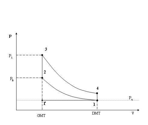
The principles underlying the combustion engine focus on one concept: burning a chemical to obtain energy and then using this energy to do work. This energy is obtained by burning the gasoline that is put into the automobile. In an automobile, a controlled process called the 4-stroke cycle, or Otto cycle, is utilized to extract the work from the gasoline. The Otto cycle can be viewed as four individual steps:
1. Intake: The piston moves from top to bottom, creating a slight vacuum. This pulls fuel and air into the chamber. When the piston reaches the bottom of its course, the fuel intake valve is closed. This position is normally called bottom dead center.
2. Compression: The intake valve is then closed, and the piston moves upward and pressurizes the air/fuel mixture. An electrical spark is ignited to burn the gasoline. The mixture burns very quickly and the expansion of the exhaust gases causes a rapid rise in the pressure of the system
3. Power: As the pressure increases, the piston is forced downward. This is the only point during the cycle that usable power is actually generated by the engine.
4. Exhaust: The piston then begins to move upward. Simultaneously, a valve is opened to let the exhaust gases leave [3].
When the engine goes through steps 1-4 once it is called a cycle (Fig. 1), and by repeating cycle after cycle the engine can use the energy gained from many small ignitions to move the vehicle. The movement of the actual vehicle is the result of transferring the cyclic movement of the piston into the rotary movement of the wheels. This distribution is facilitated through the use of a crankshaft, which is connected directly to the pistons. As the pistons go up and down, the crankshaft is forced to rotate. This rotation is then indirectly coupled to the wheels by the front and rear differentials after being geared by the transmission. Ultimately, the result is that as the engine cycles the wheels can be made to turn by putting the car “in gear.”
Driver Control of the Cycle
We can now look at this process with regards to the familiar responses of the car while driving. By pressing the gas you are telling the car to allow a larger volume of gasoline and air into the piston. Then, as you release the pedal, less gas is allowed in. Through this mechanism the driver is then able to control the amount of energy acquired by the engine and thus the energy converted into movement. Until recently, the device that controlled the fuel intake mechanism was the carburetor. However, the fuel injection system has since proven to be more efficient and reliable and has made the carburetor obsolete. These devices each control fuel intake by opening or closing a device called the throttle valve, which regulates the precise volume of gasoline and air admitted into the piston.
Traditional Methods to Increase Available Power from the Otto Cycle
In pre-1970 automobiles, more energy was acquired from each stroke using two mechanisms: by increasing piston size and the amount of oxygen available during the combustion cycle.
Larger Pistons
By increasing piston size, we can in turn increase the stroke size [4]. There are actually two benefits to doing this: 1. by making the stroke larger, more gasoline can be delivered, and 2. the delivered gasoline can be compressed more, yielding more energy. This is where we get numbers like 450cc (cubic centimeters) or 2.3 liter-these numbers refer to the displacement, which is the difference of the piston volume between BDC (lowest) and its highest position. However, to make the stroke larger the piston chamber must also be made larger. Larger engines require more raw materials, mostly steel, and thus become prohibitively costly. Also, much of the extra energy acquired by increasing the piston’s size is lost. This is because more energy is required to change the direction of a more massive piston from up to down during the cycle, decreasing overall fuel efficiency [4]. In addition, fuel efficiency may drop so much that it would fall below the federally mandated minimums, in which case the car could not be considered “sellable” in the United States.
More Oxygen
The second alternative is to increase the efficiency of the actual combustion process. During the combustion process not all of the fuel actually burns [5]. This is called incomplete burn and results in a loss of efficiency. Oxygen is required to make things burn quickly and also efficiently. You can observe this when you blow on a burning match or fire gently and the flame grows larger. Normally, air and fuel enter the combustion chamber due to the pressure gradient (a reduced pressure inside the piston due to the downward motion of the first step of the Otto cycle), but can be expedited with the use of turbo and superchargers [5]. This is a much easier way to get a relatively large amount of energy from the engine without adding a significant burden. Since inefficiently burned fuels are commonly associated with harmful emissions like carbon monoxide and sulfides, adding devices to increase the fuel efficiency has additional benefits by creating cleaner running cars [5].
Fuel Injection Systems
Despite the efficiency benefits that can be gained by increasing oxygen flow to the engine, there are definite limitations that cannot be overcome by brute force. One reason is that charged (e.g. turbo or supercharged) engine systems are made of pumps to force the oxygen into the piston before ignition [5]. The pumps require a substantial amount of energy to function and have a serious problem with overheating. Because of this they often fail as a result of heat fatigue and thus require costly maintenance to remain operational. A system that works in concert with the charging mechanisms to increase efficiency is fuel injection [6]. The concept behind fuel injection is to spray a fine mist of gasoline (like that from an aerosol can) into the piston, in contrast to the large drops that traditional fuel intake carburetor valves provide [6]. By injecting fuel in this manner, more oxygen is injected “between” the mist particles. Ultimately, this increases the efficiency of combustion and the available power. Because of these overwhelming advantages, carburetors have been completely phased out from all US production automobiles since 1990 and replaced with fuel injection systems [7].
Fuel injection works on a commonly known principle: it is much easier to burn the smaller twigs and leaves (i.e. misted gasoline delivered using fuel injection) than it is to burn a large log (a large droplet from standard intake valves). There is, however, a practical and optimal limit to the size of the mist particles-about 10 micrometers (about one-half the width of human hair) [5]. Because of the desire to obtain the highest efficiency from the burned gasoline as possible-constrained by precise technical conditions like particulate size-fuel injection systems have become very complicated. This explains the slow development of such systems until recently when computers could be utilized to model their behavior.
Divergence of Fuel Intake Systems
With the introduction of an injection system a new degree of freedom was simultaneously introduced, causing a divergence in the types of combustion engines. The first is called homogenous. This type of combustion engine is the kind discussed so far, where the gasoline is simply let into the piston via a simple port intake mechanism. It then diffuses to create a homogenous [5] mixture of fuel and oxygen throughout the chamber. In contrast, the fuel injection system allows the manufacturer to precisely control temporal (the exact time during step 1 of the Otto cycle that fuel is injected) as well as spatial placement (the shape of the jet that is sprayed by the injector) of the fuel spray. This new type of engine is called the stratified charge engine [5]. In these engines, “the aim is to stratify the charge in the combustion chamber, i.e. to have a pocket of rich (fuel) within a larger body of weak air/fuel mixture, and to ensure that the rich, easily ignitable area surrounds the spark at the point of ignition” [5]. In general these engines produce highly desirable results, however are limited to some degree by the “precise mixture control and manufacturing costs” [5].
Computers and Fuel Injections
Computer Aided Design (CAD)
While the industry pursued serious research in fuel injection early in the mandates to reduce pollution and increase fuel economy, in general, major developments came through the process of trial and error [8]. However, the introduction of the microcomputer age removed this hurdle in the design and implementation of fuel injection systems because the systems could now be simulated in a virtual stroke in a computer and then modified to run with new parameters in minutes; this is a process that would have taken weeks or months as dies were cut and re-cast under traditional industrial practice [9]. Design was further aided by complex models, which predicted how the fuel and oxygen would interact in the piston and calculate the efficiency of the burn [10]. In addition to these fabrication benefits, direct increases in efficiency were soon seen. For instance, one major advance in improving efficiency was introduced when computer simulations found that by injecting fuel at various angles a much finer and more controlled mist could be obtained [10].
Computer Aided Implementation (CAI)
Digital logic, and more specifically micro-controllers (small computers), also revolutionized the actual implementation of fuel injection systems. Previously, the actual delivery mechanism of fuel was mechanical and was generated from the injector forcing gasoline though a comb filter, producing a relatively inconsistent mist. However, with the advent of modern processing technology, the timing of one, or even several separate injectors can be precisely controlled in each piston. In addition, the timing and amount of fuel released can be varied depending on the demands placed on the engine by the driver. Honda has introduced this injection technology in force through their trademarked VTEC line. VTEC stands for Variable Valve Timing and Lift Electronic Control and is a system that constantly monitors the demands placed upon the engine. It then adjusts not only the fuel injection timing but also other relevant factors such as the intake valve open duration, called its “pulse width”. According to Honda, “[VTEC] technology solves the age-old compromise between tuning an engine for peak torque or peak horsepower, and provides the best of both worlds. With VTEC, the engine delivers ample low-rpm torque and high-rpm power without sacrificing either.”
Additions like VTEC bring us nearer to an emergence of a modernized hot-rod. Cars will be equipped with computer-designed fuel injection systems and employ the latest computer sensors and enjoy improved functionality. This will eventually return to them the power and muscle they once possessed and that American drivers desire, while reducing harmful emissions and increasing the overall efficiency of each gallon of gasoline burned.