The aircraft carrier is the centerpiece of the United States Navy because of its ability to transport aircraft all over the world. The main component of these ships is their ability to launch and land jets in such a small space. But with so much chaos in such a small area, engineers have had to design simple yet effective devices to help manage the process. The catapult system is used for taking off, while the Fresnel lens and arresting wires are used to help the pilot land. These systems have been in place for several decades, and even though technology will improve drastically within the next 20 years, the future systems will continue to be based on these initial designs.
The Floating Airport
Aircraft carriers have been the centerpiece of the United States Navy since World War II despite the fact that their most basic and important function, launching and landing fighter jets on a ship in the middle of the ocean, proves to be a very difficult task. Due to the extremely limited runway space on the decks of these mobile machines, engineers have been forced to develop powerful systems to accelerate and decelerate aircraft in a very short period of time.
Ship Basics
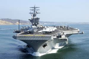
The Navy currently uses Nimitz class aircraft carriers, which are typically 1,094 feet in length and have deck space of approximately 4.5 acres, the size of four football fields (see Fig. 1). Below deck the ships hold up to 80 aircraft, 6,250 people, 2 nuclear reactors, and all the supplies needed for tours that can last several months [1], [2].
In order for the aircraft carrier to act as a true traveling airport, the pilots and crew rely on three key elements to launch and land aircraft safely. First, four catapults are specially developed to launch planes at high speeds. Second, a lighting system known as the Fresnel lens, or the “meatball” system, lets a pilot know if the plane has the correct altitude and position when approaching to land. Third, four arresting cables are in place to bring the plane to rest in less than 320 feet [3].
Launching From A Catapult
Aircraft typically require long runways in order to gather enough speed so they can successfully take off. Since the runway length on an aircraft carrier is only about 300 feet [3], compared to the 2,300 feet needed for normal aircraft to take off from a runway [4], engineers have created steam-powered catapults on the decks of carriers that are capable of launching aircrafts from 0 to 150 knots (170 miles per hour) in just 2 seconds [5]. The takeoff system can be broken down into two components – the above ground and below ground operations.
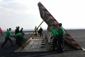
Above deck, the crew hooks the aircraft’s front wheel, or nose gear, to the catapult using a tow bar. The tow bar hangs off the front of the nose gear so the catapult can pull the aircraft [2]. In order to prevent harmful jet discharge from going into unwanted places, a jet-blast deflector is placed directly behind the aircraft, pushing the discharge up into the air (see Fig. 2). The pilot then pushes the engine to full throttle, creating a forward thrust that would traditionally move a jet forward [5]. A holdback bar is in place to prevent any motion at this time, despite the thrust of the jet.
Once the force from the catapult is added to the thrust of the jet, the excess force will cause the hold-back bar to release and the jet will move [2]. This is because the hold-back bar can only hold the force from the jet at full thrust, but not the additional force of the catapult.
Below Ground
Below deck, steam is pumped into a capsule at extremely high pressures. Once a valve is released, steam travels up a long tube that runs the length of the catapult. The pressure from the steam travels to several pistons, which are locked in place until the signal for their release is given. The pistons are attached to the catapult above by a pulley system located in a crack running the length of the runway [6].
Once the aircraft is at full throttle and the steam is creating pressure below deck, the pistons are released and pushed forward at high speeds. The force causes the holdback device, which is designed only to hold the force from the thrust of the jet, to release and shoot the jet from the ship into the air.
After completing its task, the catapult must be stopped quickly. A water brake system is attached to the end of the launch tube. When the pistons hit the water brake, pressure from the water in the tube forces the pistons to quickly come to a halt [7]. The pulley system then rapidly retracts the catapult so that the next aircraft can be hooked up for launch. The retracted pistons push the steam through separate tubing so that it can be reheated and reused for later launches [6]. The entire process takes around 20 to 30 seconds to complete [2].
The Landing Process
Landing on an aircraft carrier is often described as the toughest task for a Navy pilot. The pilot has to line up with the runway correctly, come in at the correct angle, and stop the plane in a short distance for a successful landing. For many this would be an unnerving task, but luckily engineers have devised two systems to help accomplish these tasks – the Fresnel lens and the arresting wires.
Lining Up For Landing
The Fresnel lens optical landing system provides guidance for correctly landing on an aircraft carrier [2]. The lens is located on the side of the runway so that it can be seen by the pilots throughout the entire landing process.
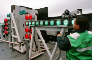
The optical landing system consists of a horizontal bar of green lights and a vertical bar of red lights on both sides of the “meatball” [3]). The “meatball” is the centerpiece that consists of five amber colored lenses (see Fig. 3). Certain lenses will light up one at a time depending on the angle the plane is in relation to the “meatball.” This causes the center light to appear to be moving up and down in relation to the horizontal green bars on the sides. In order to safely land, the pilot tries to keep the center amber lens horizontal with the green bar throughout process [2]. If the pilot gets too low, the amber light will turn red indicating that the aircraft is dangerously low and risks hitting the back end of the aircraft carrier. The red lights around the green horizontal bars will be flashing if the carrier is not able to receive the aircraft, and so the jet must keep circling or find another place to land [3].
Touching Down
The most dangerous part for the pilots is the touchdown and subsequent deceleration caused by the arresting wires. Not only does it take incredible skill to pull off this landing maneuver, but success also depends greatly on the ground crew avoiding any errors throughout the operation. Before touchdown, the pilot lowers the tail hook. The tail is a long metallic bar that hangs just inches above the surface of the carrier. When the aircraft lands, the hooked end of the tail snags one of the four arresting cables, stopping the aircraft. Although the cables are simple in structure, there is a great risk of something going wrong. Good pilots hit the second or third cables rather than the first or fourth, because these wires will keep the pilot from running into the back of the carrier while still allowing room for takeoff should they miss their target. Once the wheels hit the deck, the pilot immediately pushes the aircraft to full throttle. This is to ensure that if the tail hook misses the arresting wires, the aircraft can still have enough speed to quickly take off again at the end of the runway [2].
Before the aircraft lands, a member of the arresting-gear crew inputs the weight specifications of the incoming jet and checks the statistics very carefully [5]. If the inputted weight is too large, the plane might be stopped too quickly, causing damage to the jet. Even worse, if the inputted weight is too low, the aircraft will not be stopped in time and the jet will fly off the runway into the water. Although the danger is always prevalent, extensive training and practice make these types of catastrophes rare.
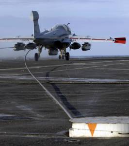
If everything goes right and the arresting cable is engaged, the cable is pulled out through the ground and slows the plane. Operated by pulley systems, both ends of the cable meet up with a piston inside a cylinder running parallel beneath the deck wires above (see Fig. 4). The cylinders are filled with a varying amount of fluid depending on the weight of the craft. As the wire is pulled, the pistons move through the tube, slowly forcing the fluid out of the cylinder. The force from the fluid slows down the initial tug on the pistons, which in return slows down the arresting wires and the attached plane [6]. Once the plane is at a complete stop and powered down, the tail hook is released and the arresting wires are pulled back and readied for the next aircraft to land [5].
Future Improvements to the Aircraft Carrier
New systems for aircraft carriers are being developed and integrated into the Nimitz class ships. The USS Ronald Reagan, launched in July of 2003, changed the angle of the landing runway in order to create more room in the front of the carrier and longer catapults [3]. The arresting wires and their engines were both strengthened. All of these changes made the carrier capable of carrying new aircraft that weigh more and improved launch and landing times [8].
The CVN-21 class of aircraft carriers will soon replace the Nimitz class as the standard in the United States Navy. The USS Gerald R. Ford will be the first carrier of the next generation [3]. In addition to improved deck size and positioning, the USS Gerald R. Ford will replace the steam-powered catapult and implement an Electromagnetic Aircraft Launch System, or EMALS [1]. Instead of using steam to push the pistons down the runway, magnets will create the force on the catapult. The final system is still being engineered, but it will be similar to the current magnetic system that is used to propel some roller coasters.
These systems will greatly increase the safety of the launch and landing systems, while decreasing the maintenance, since they will be less reliant on humans, and thus less susceptible to human error. The future carriers will be able to stay out at sea longer because they will require 300-500 fewer sailors [9]. By improving current systems rather than creating an entirely new aircraft carrier, the Navy has increased the speed in which the new line can be introduced, and has decreased the cost [9].
By using the current technology systems as the model for the future designs, the Navy is demonstrating how simple yet effective the original design principles really are. Engineers have created an aircraft carrier that has withstood the test of time and will continue to be used, in one form or another, well into the future.