In Spring 2002, Russell Myers was a junior at the University of Southern California pursuing both an electrical engineering degree with an emphasis in digital signal processing, and a minor in music, studio performance guitar. Originally from Texas, he enjoyed wrestling bulls and overdriving amplifiers in his quasi-free time in college.
Audio distortion has become an accepted method of musical creation. A discussion of the wave properties of sound, the origin of distortion (due to both wave physics and audio device technology), and an overview of many types of distortion, including hard and soft clipping, even and odd harmonic distortion, speaker overdrive, amplifier non linear operation and intermodulation, are offered.
Introduction
For decades scientists and engineers have debated the source of the unique artistic genre commonly referred to as rock music. Several reputable sources claim that Elvis, with his Blue Suede Shoes, greased hair, and snarling lip brought together the raw, blues-driven sound. Others vehemently argue that The Beatles are responsible for fusing melody with sexual innuendo; after all, John Lennon was the first to harness guitar/amplifier feedback as an effect on the track, “I Feel Fine.” Surprisingly, the answer to this troubling enigma lies in the fact that rock & roll’s source is not so much a who, but a what: rock and roll’s source is the signal processing effect known as distortion.
For most all engineering applications, distortion is actually an unwanted effect; by definition, it is the “undesired change in the waveform of a signal.” Our contemporary digital age of electronics is designed to limit distortion in order to improve signal accuracy. Although this may all be well and good, in the aural world musicians and engineers have embraced this phonetic accident, and with it developed an unlikely tool for artistic expression. Auditory distortion most likely was accidentally discovered in a live musical setting. In order for the sound to reach an audience spread across a large area, the speaker amplitude level must be relatively high. When these levels surpass the amplifier’s linear range of operation, amplifier overdrive occurs, and the result is distortion. Given that rock music and loudness are inextricable entities, although first mildly associated with the genre, distortion has quickly become essential when one defines rock [1].
Although its birth was an unplanned event, audio distortion has matured into a science of its own. The two main components in distortion are the original signal and the amplifier through which this signal is processed. The processes by which distortion is produced vary as much as the sounds; since the 1950’s engineers and musicians have worked together to produce endless tone and fuzz combinations.
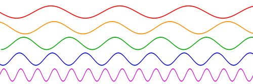
To some it may just be noise, but auditory distortion is actually a highly complex phenomena (Fig. 1). Physics, mathematics, musicianship and electrical engineering must all coalesce in order to manufacture a desirable sound. The accidental circumstance of its discovery explains the reason for its complexity; engineers must reproduce this chance accident consistently and specifically.
The Nature of Sound: Waves 101
In order to understand the electro physics of distortion, one must first gain a basic understanding of the nature of sound. Sound is produced when an event causes a mechanical oscillation that disturbs the adjacent medium, namely air. The air molecules then begin to oscillate with the same frequency as the source and create a pressure wave having periods of compression and rarefaction. When this pressure strikes the human ear drum, the energy is then converted back into mechanical form, and is ultimately processed by the brain as sound. Although sound is independently transferred by a longitudinal wave, the actual information is packaged in a superposition of sinusoidal wave.
Sound’s infinitely unique possibilities result from altering the characteristics of sound waves. In music, a note’s pitch is directly related to the wave’s frequency. Likewise, the auditory loudness of a sound is dictated by the wave’s amplitude. Thus, in order for an opera singer to achieve glass-breaking sound, she must produce a wave high in both frequency and amplitude.
Harmonics: Fuzzy Math
The auditory distortion that connoisseurs on the subject may refer to as “crunchy, fuzzy, or dirty” is more accurately defined for musical purposes as harmonic distortion [2]. A sound wave’s harmonics are the integer multiple of its initial, or fundamental, frequency. Harmonics can be even or odd depending on the whether the fundamental frequency is multiplied by an even or odd coefficient.
On the guitar, a note’s 2nd harmonic has twice the frequency, making it one octave higher. For example, the A has a frequency of 440 Hertz, meaning the string vibrates 440 times per second. Its second harmonic is then 880 Hertz, and 1320 Hertz for the third. Striking both notes simultaneously produces two sinusoids of differing frequencies that interfere with each other; this is where the fun begins!
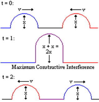
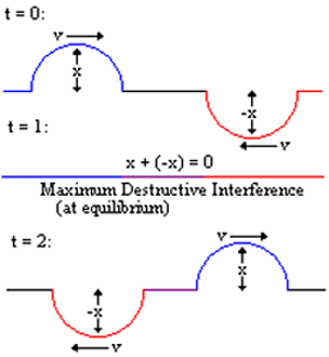
Waves with differing frequencies effectively interfere with each other constructively (Fig. 2) and destructively (Fig. 3), depending on the cycle. This interference results in a composite wave, which has areas of higher amplitude due to the constructive and reduced amplitude regions from the destructive.
Due to the effects described by Fourier’s Theorem, interference from odd-numbered harmonics squares off the composite wave in slide(c); thus, infinitely increasing the number of harmonics ultimately brings the composite wave asymptotically closer to the square wave [3]. As the wave approaches a perfect square, it produces the flat, percussive sound commonly used by heavy metal bands such as Korn and Slipknot.
When wave portions are lost due to the squaring effect, it is referred to as “clipping.” Wave amplitude is constant in these regions; this translates to an absence of oscillation, meaning the sinusoid is incomplete.
So far we have spoken only of odd harmonics, but even frequency multiples have their own flavor as well. Even order harmonics change the waves pulse width, making the bottom component wider than the top. This creates a creamier tone with a fuller sound that is sometimes achieved by running a Les Paul guitar through a Marshall cabinet amplifier. The reason most guitarists prefer tube amplifiers is specifically because of the even order harmonics they produce. However, even harmonics must be limited since too many would chop off the wave’s bottom half entirely. This would result in a vintage “fuzz box” type of sound, similar to that used on The Beatle’s “Revolution” guitar intro but only much, much worse [2]. The best harmonic distortion results from a combination of both: mostly odd partials to chop the signal, and even partials to flavor it.
Amplifiers: The Womb of Fuzz
With a cursory mathematical discussion of harmonic distortion laid out, the next step is to investigate the guitar amplifier as the vessel from which this phenomenon is produced. The guitar amplifier is the means by which the clipped wave we produced mathematically occurs in real world applications. There are two basic types of guitar amplifiers: valve and solid state. The amplifier type is described by its structure: either a vacuum tube or a semiconductor transistor. Both designs serve the same function with different electrical and physical means, but have vastly different affects on the amplifier’s audio properties.
In essence, the guitar amplifier multiplies an electrical input signal by the voltage gain and produces an audibly louder sound [4]. This is accomplished with three primary components: an input signal, the valve, and the speaker cone output. In a valve amp, the current supply creates an electric pressure behind the input signal. A wire grid with a voltage potential serves as a gate to hold this pressure; adjusting the grid’s voltage then allows for the signal-carrying electrons to pass through [5]. Increasing the gain actually increases the electron flow, translating to a higher current. The output signal’s amplitude is a direct relation to the valve’s output current. To increase the overall amplification, this procedure can be repeated with a system of tubes stacked in series (Harris 4).
The amplified signal must then be converted back into acoustic energy by the speaker cone output. The diagram below details several speaker system workings, but we will focus only on the magnet structure, the voice coil assembly, and the cone. The magnet structure consists of one permanent magnet attached to the speaker base, and one electromagnet attached to the speaker cone. The electromagnet is created by the voice coil assembly with a basic electromagnetic principle: when a current in a wire is driven through a coil, it produces a magnetic field pointing through the coil. The electromagnet receives its power from the amplifier’s output signal in the form of an alternating current. As the current oscillates, it changes the magnetic field’s direction to the exact opposite. Since the stationary magnet maintains a constant polarity, the attractive/repulsive forces change with the electromagnet’s instantaneous polarity [6]. Attaching one magnet to the speaker cone serves to convert these magnetic forces to mechanical motion. The speaker then oscillates with the output current’s frequency and amplitude, moving air to create an audible pressure wave. The resultant wave is exactly proportional to output current.
Weren’t We Talking About Harmonic Distortion?
With all the scientific pawns in place, let us now attack the roots of harmonic distortion. Guitarists often play valve amplifiers at the cusp of their maximum output and sometimes beyond. While others would consider this an attempt to play at obnoxiously loud levels, musicians intentionally push amplifiers to their threshold capacity for the distorted effect that only occurs in this non-linear region at the signal extremes.
When a valve amplifier is driven exactly at its amplitude threshold, the speaker cone is oscillating through its maximum linear cycle; while remaining in this linear region, no distortion is occurring. Physically, the speaker cone is moving back and forth near its elastic limit. As the amplitude is increased, the speaker begins to leave its linear range, and saturation occurs; in music, amplifier saturation is referred to as overdrive [2]. With overdrive, the speaker system simply cannot handle the amplitude the output current demands. The speaker responds by holding the signal amplitude at its loudest capacity until the output current falls back into the linear range.
The most interesting aspect of this phenomenon is the frequency’s behavior in the non-linear range. A sinusoid results with its maximum upper and lower levels “cut off,” and is said to be have undergone soft clipping [1]. Increasing the amplitude within and beyond the overdrive range causes the speaker to leave its linear range sooner. The signal then maintains constant amplitude for a longer period, and is said to have undergone hard clipping. The graph below exhibits this effect with one perfect, and two imperfect sinusoids with varying degrees of distortion.
Driving the amp’s coil into its non-linear range produces the harmonics necessary to distort the signal. The mathematically produced harmonics we spoke of earlier are produced naturally through speaker saturation [5]. The speaker maintains a relatively constant amplitude, but keep in mind this region is non-linear so it allows for several surprises. In the clipped regions the speaker cone does not oscillate, but vibrates. These tiny fluctuations, occurring at the overdriven level, are the hues that give the distortion its unique color. However, these vibrations are not chaotic, but are dependent on the properties of every device involved. Not only do the instrument and amplifier contribute, but every detail within each: from the instrument’s wood and pickups to the amplifier’s tubes, internal circuitry, and speaker design [1]. This is the reason some become obsessed with every detail of their musical production.
Operating in this non-linear range gives birth to an entirely new host of properties. Some of these byproducts are favorable and allow for increased musical range, while others can be limiting. One of these bittersweet effects is inter-modulation distortion. Inter-modulation distortion is produced by the interference of two or more notes played simultaneously, and it effectively serves to add two extra notes: one with a frequency equal to the difference of the two, and one with a frequency equal to their sum [7]. While this can be desirable when playing simpler two and three note power chords, strumming all six together produces a muddy pit of over fifteen notes. Rarely does probability allow for such a busy combination to sound euphonic, and it usually sounds harsh. This is because not all notes produced by inter modulation distortion are harmonics of the originals; this type of distortion is not harmonic and sounds unmusical.
Conclusion
Ironically, the phenomenon some have spent careers eliminating, others have devoted lifetimes to harnessing. We have encountered difficulty in finding the means to eliminate distortion and struggled even more to replicate it. Harmonic distortion not only exhibits our incessant drive for absolute perfection, but it champions man’s creative resiliency to carve an accident into art.
References
-
- [1] GM Arts. “Guitar Amplifiers- Overdrive and Distortion.” GM Arts Homepage. Internet: http://users.chariot.net.au/~gmarts/ampovdrv.htm, 1 May 1996 [21 Jan. 2002].
- [2] Blackstone Appliances. “Distortion 101.” Blackstone Appliances, Inc. 12, Internet: http://www.mindspring.com/~j.blackstone/dist101.htm, Feb. 1999 [1 Jan. 2002].
- [3] Boars Porat. A Course in Digital Signal Processing. 1st ed. New York, NY: J. Wiley & Sons, Ltd., 1996.
- [4] Svetlana Electronic Systems. “How a Vacuum Tubes Works.” Svetlana Electronic Systems, Inc. Internet: http://www.svetlana.com/docs/tubeworks.html#INSIDE, 1 June 2001].
- [5] David Huber and Robert Runstein. Modern Recording Techniques. 4th ed. Boston, MA: Focal Press, Inc.,1997.
- [6] Tom Harris. “How Speakers Work.” How Stuff Works, Inc., Internet: http://www.howstuffworks.com/speaker1.htm, 1 Jan. 1998 [2 Feb. 2002].
- [7] R.G. Keen. “A Musical Distortion Primer.” Geo-Fex Cybernetic Music. Internet: http://www.geofex.com/effxfaq/distn101.htm, 1 Jan. 1993 [1 Jan. 2000].
- [8] Paul Tipler. Physics for Scientists and Engineers. 4th ed. New York, NY: W.H. Freeman & Co., 1990.